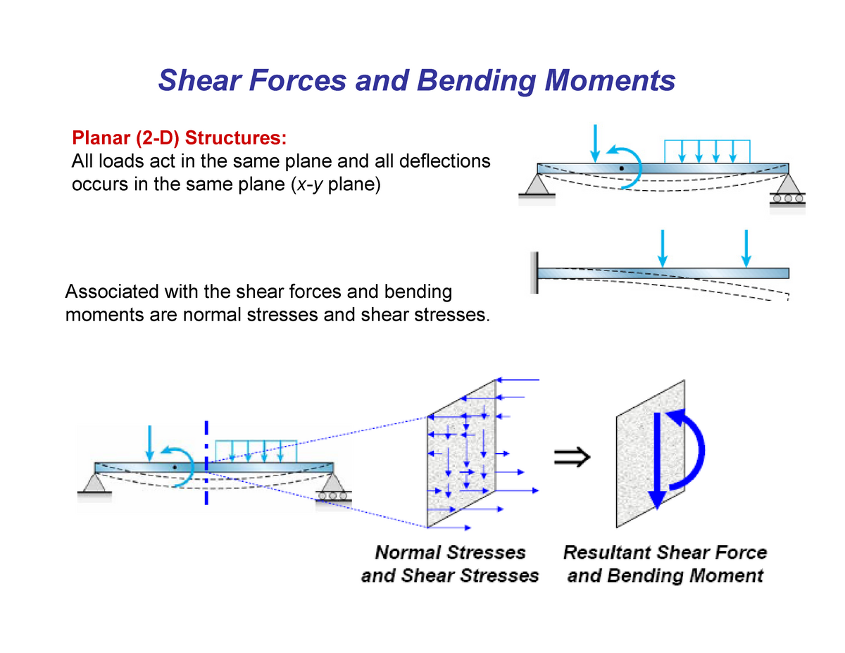
Bending moments Lecture notes 712 Shear Forces and Bending Moments
The bending moment is a measure of the force applied to an object that causes it to bend, and is calculated by multiplying the force by the distance from the point of bending. Bending moment is a crucial concept in the field of engineering and design. It is used to determine the strength and stability of structures such as bridges and buildings.

Shear force & Bending Moment Formulas With Diagram CCAL Shear force
The bending moment is the algebraic sum of the applied load to the given distance from the reference point. Bending moments will also be caused due to the sum of applied moments from the reference point. The bending moment is an important part of the GATE CE syllabus.

Bending moment diagram of nine piles. Download Scientific Diagram
A bending moment describes the internal force that leads to bending of a structural element such as a beam due to loading. In easier words, a bending moment refers to the tendency of a structural element to deform due to external loading (self-weight, snow, wind, people etc.).
What is bending moment? Understand in simple terms
Bending moment at a section of a structural element is defined as the reaction developed in a structural element when an external force or moment is applied to the element that causes the element to be bent. Bending moment at a section of beam is calculated as the algebraic sum of the moment of all the forces acting on one side of the section.
bending moment Liberal Dictionary
Shear force and bending moment diagrams are used to analyse and design beams. By showing how the shear force and bending moment vary along the length of a beam, they allow the loading on the beam to be quantified. They are often used as a starting point for performing more detailed analysis, which might include calculating stresses in beams or.
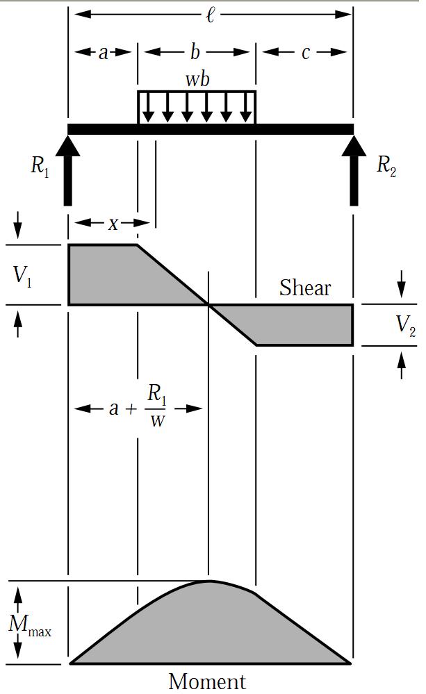
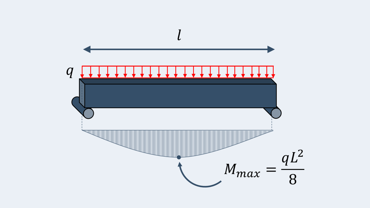
Simply Supported UDL Beam Formulas Bending Moment Equations
Bending moment is a measure of the internal force or moment that causes a structural element to bend. A bending moment diagram is a graphical representation that illustrates the variation of bending moments along the length of the structural element. In this article, we'll discuss bending moment diagrams in detail and how to construct them..
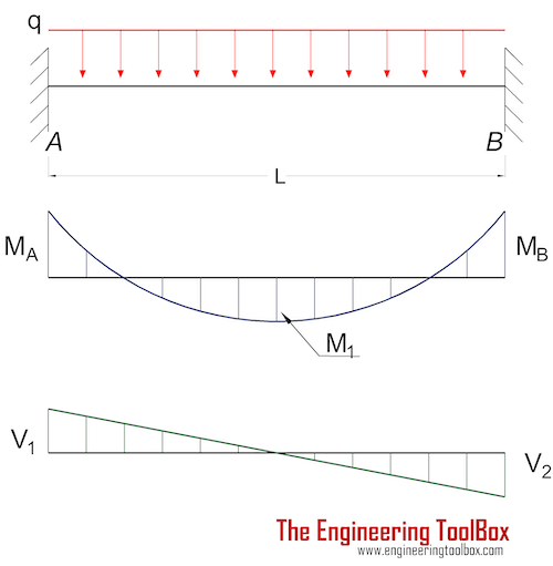
Beams Fixed at Both Ends Continuous and Point Loads
Note that the moment increases with distance from the loaded end, so the magnitude of the maximum value of \(M\) compared with \(V\) increases as the beam becomes longer. This is true of most beams, so shear effects are usually more important in beams with small length-to-height ratios. Figure 3: Shear and bending moment diagrams.

Cantilever Beam Shear Force & Bending Moment Diagram YouTube
When a force is applied at the free end of a body which is fixed at another end, a moment of force arises in the body that can bend it. This moment is called the Bending Moment. One can observe such bending in the cantilever beam. The external force must be applied perpendicular to the length of the beam or rod which is known as the moment arm.

The 25+ best Bending moment ideas on Pinterest Shear force
Bending moments are produced by transverse loads applied to beams. The simplest case is the cantilever beam , widely encountered in balconies, aircraft wings, diving boards etc. The bending moment acting on a section of the beam, due to an applied transverse force, is given by the product of the applied force and its distance from that section..
Bending Moment The Best Equations to know (Free Calculator) Tribby3d
A bending moment is a force normally measured in a force x length (e.g. kNm). Bending moments occur when a force is applied at a given distance away from a point of reference; causing a bending effect. In the most simple terms, a bending moment is basically a force that causes something to bend.
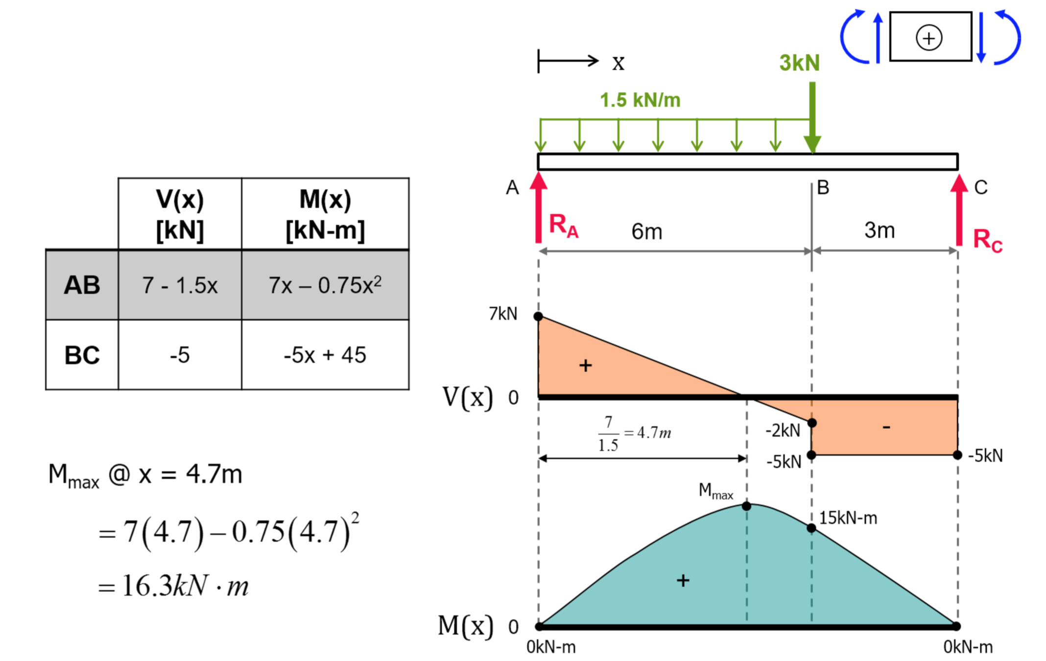
Exercise Shear Force & Bending Moment Diagrams (Solution) TU Delft OCW
In solid mechanics, a bending moment is the reaction induced in a structural element when an external force or moment is applied to the element, causing the element to bend. [1] [2] The most common or simplest structural element subjected to bending moments is the beam.

Learn How To Draw Shear Force And Bending Moment Diagrams Engineering
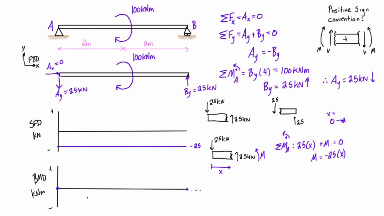
This section covers shear force and bending moment in beams, shear and moment diagrams, stresses in beams, and a table of common beam deflection formulas. Contents Constraints and Boundary Conditions Shear Force and Bending Moment Sign Convention Shear and Moment Diagrams Bending Stresses in Beams Shear Stresses in Beams
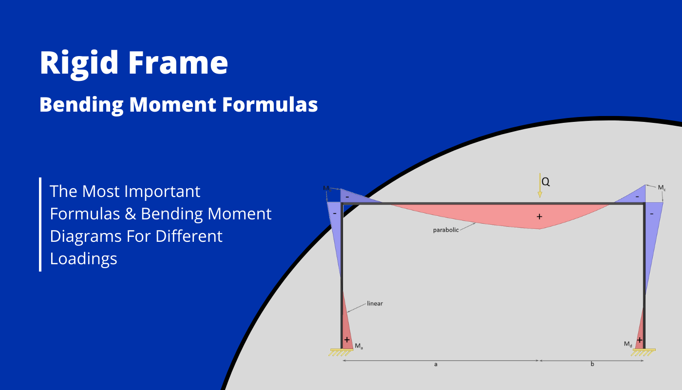
Rigid Frame Structure Moment formulas Different loads Structural
As its name implies, the bending moment occurs when a force is applied to a structural element (such as a column or beam), and that external force causes the element to bend and ultimately fail.

21 Questions & Answers On Bending Moment Diagram
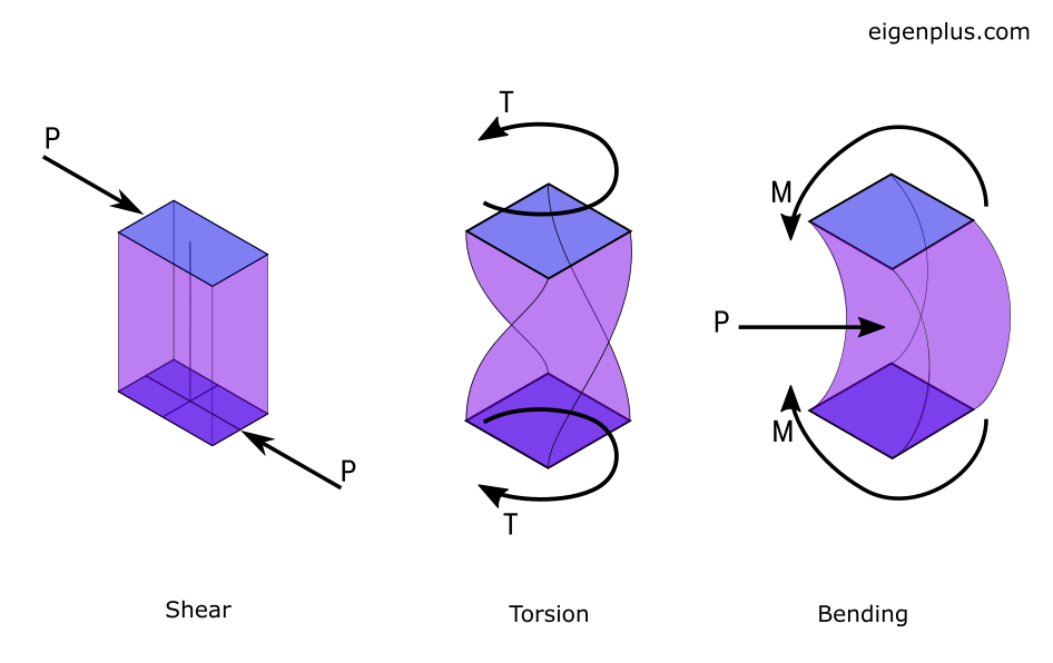
Shear force and bending moment are one of the most important concepts in civil engineering under structural engineering. Shear force refers to the force that acts parallel to the cross-section of a structural element, while bending moment is the moment that occurs when an external force is applied to the element causing it to bend.

Elastic bending moment diagram (BMD) for 2span purlin system, together
The bending moment is defined as the external load is applied in a beam element to bend. The bending moment is generated. The internal reaction loads in a cross-section of the structural elements can be resolved into a resultant force and a resultant couple for equilibrium the moment created by external force must be balanced by the couple.

Bending Moment Types, Formula, Limitations, Bending Stress
Bending moment (BM). Bending moment function. By definition, the bending moment at a section is the summation of the moments of all the forces acting on either side of the section. Thus, the expression for the bending moment of the \(5k\) force on the section at a distance x from the free end of the cantilever beam is as follows: \(\begin{array}{l}